Testing e-bike controllers, throttles and brake cut-offs before a rider meets traffic
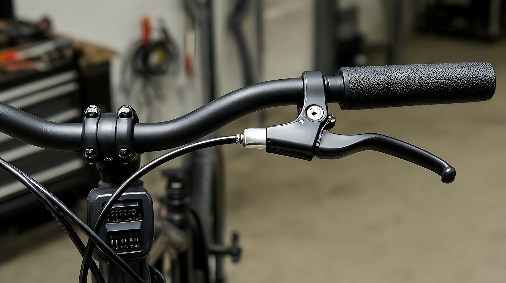
An e-bike control system has one job that matters more than range or top speed: it must not deliver power when the rider does not ask for it. Every other defect is an inconvenience. An unintended surge at a junction is a different category of problem, and it usually traces back to a throttle, a PAS sensor or a controller that was never tested in the state it ships in.
The sequence below is written for the commuter e-bike class, where controllers are commonly 36 V or 48 V with integrated PAS and a thumb throttle. It is designed to be run on a stand in fifteen minutes per unit, with a meter and a load, before the bike is handed to a rider.
1. The order of tests matters
Test the brake cut-off before the throttle, and the throttle before the PAS. If the brake cut-off is faulty, the throttle test will look normal while the bike is unsafe, because the brake is the only thing that stops power in an emergency. Reversing the order hides the most dangerous fault behind a passing result.
Then test the standstill behaviour: power on, rider off, throttle closed, and confirm the motor does not move the wheel for ten seconds. A controller that creeps at standstill is a controller with a throttle offset that has not been learned or a hall sensor that is misaligned.
2. Brake cut-off, both levers
Test each brake lever separately with the throttle held at 20%. Power must drop within the distance the specification states, and it must drop to zero and stay there until the lever is released and the throttle is returned to closed. A system that resumes power when the lever is released, with the throttle still open, is a system that will launch the bike.
Check the cut-off type: a mechanical switch in the lever, a hall sensor, or a brake light signal. Each fails differently. Mechanical switches fail open, which means no cut-off; hall sensors fail when the magnet moves; a brake light signal can be defeated by a bulb failure on some controllers. Test the type you actually have.
3. Throttle linearity and return
Measure the throttle output voltage or the PWM duty at five positions from closed to full, and check that the response is monotonic. A throttle that jumps from 1.2 V to 3.4 V over the first few degrees of travel gives the rider full power in a gesture intended to be gentle, and it is the most common cause of a low-speed surge complaint.
Then test return: release the throttle from full and watch the output fall to the closed value within the specification, usually under a second. A throttle that hangs at part-open is usually a binding grip or a stretched cable, and it is cheap to fix at the bench and expensive to explain at a hospital.
4. PAS sensor behaviour
A cadence sensor should start assisting after one to two crank rotations and stop within a defined time after pedalling stops, typically under a second. Test at a low cadence and at a high cadence; some sensors miss pulses at high cadence, which produces a stutter that riders describe as a misfire.
Test the direction: a sensor fitted on the wrong side or with the magnet ring reversed can read backwards, which on some controllers produces assistance when the cranks are turned backward. That failure is rare and it is exactly the kind of thing a stand test catches in ten seconds and a road test reports as a mystery.
5. Walk mode and the low-speed envelope
Walk assist is limited by regulation in most markets, and the limit is a speed, not a power level. Measure the speed the bike reaches in walk mode on a stand and compare against the regulatory limit for the destination market. A bike that walks at 8 km/h when the limit is 6 km/h is a compliance problem, not a convenience feature.
Then check the cut-off at the maximum assisted speed. Power should taper and stop at the legal limit, not at the controller's own maximum. A controller configured for a different market will pass every functional test and fail every roadside check.
6. Water resistance of connectors
The controller connector, the throttle connector and the battery cable are the three points where water enters the system. Inspect for a proper seal, a boot or a potting compound, and confirm the connector is rated for the environment the bike is sold into. A connector that is merely tight is not a sealed connector.
Run a spray test on a sample unit and then repeat the throttle and brake tests. Intermittent faults that appear only after water ingress are almost impossible to diagnose in the field, and they are trivially easy to catch on a bench with a spray bottle.
7. Fault codes and the display
Read the fault log from the display if the controller supports it, and confirm that the log is empty on a new unit. A unit that ships with a stored over-current event has been tested at the factory in a way that the distributor was not told about, or it has already been run under load.
Confirm that the display shows the correct wheel size and speed. A wheel circumference set for a 26-inch wheel on a 20-inch bike over-reads speed by about 30%, which turns a legal bike into an illegal one on the display and makes the rider distrust the remaining range.
8. Load test and thermal behaviour
Run the motor on a brake dyno or a rolling stand at rated continuous power for twenty minutes and measure controller case temperature. A controller that rises above the specified limit at rated load will derate in service, and the rider will report it as a bike that loses power on long climbs.
Measure the phase cable temperature at the same time. Warm cables mean resistance, and resistance in a phase cable usually means a bad crimp. A crimp that is warm at rated current is a crimp that will fail at peak current, which is exactly the moment a rider asks for maximum assistance.
Repeat the load run with the battery at 30% state of charge, because a controller that behaves at full voltage may behave differently at low voltage. At low state of charge the current rises for the same power, and a marginal connector or a marginal crimp becomes a hot spot. Record the phase current and the cable temperature at both states of charge.
9. What the rider will notice, and what it means
Four complaints map to the controller: a delay before assistance, a surge from a standstill, a cut-out over bumps, and a throttle that does nothing until it is turned a long way. Each maps to a measurable condition: PAS timing, throttle curve, connector seating, and throttle dead band.
Mapping complaints to measurements before the bike is delivered turns a warranty conversation into a bench adjustment. It also builds a fault library that a distributor can share with the factory, which is how controller firmware improves between batches.
10. The record
Record brake cut-off result for both levers, throttle output at five positions, return time, PAS start and stop time and direction, walk speed, maximum assisted speed, fault log status, wheel setting, controller temperature at rated load, and the decision.
Keep the record with the serial number. When a controller fails at 2,000 km, the acceptance record shows whether the unit was already at the edge of its thermal limit on day one, which is the difference between a warranty claim and a design complaint.
11. Fleet checks that take five minutes
For a fleet in service, a five-minute monthly check catches most developing faults: brake cut-off on both levers, throttle return, PAS response, and a visual on the three connectors. That routine prevents the failures that take a bike out of service for a week.
Log the results per bike. A fleet that can show brake cut-off passing every month for a year has a defensible safety record, and that record matters more than any specification sheet when a client asks how the bikes are maintained.
Frequently asked questions
Can I test without a dyno? Yes. A stand with a adjustable friction load and a ten-minute run at 250 W is enough to see thermal behaviour on a commuter controller.
What if only one brake lever cuts off? Reject the unit. A bike with one working cut-off is a bike that will eventually be ridden by someone who uses the other lever.
Is a throttle dead band normal? A small dead band of a few degrees is normal. A dead band of 20 degrees is a defect that makes the bike feel unresponsive and encourages riders to twist harder than they intend.
Should the display hide fault codes? No. A display that hides stored faults removes the only diagnostic channel the workshop has.